Making electricity with diesel fuel is expensive, pollutes the environment, and is difficult to budget because of the exposure to global markets. Solar energy is a great alternative for communities or islands that make electricity by burning diesel fuel.
Here are the top-3 questions we get from clients about a solar-energy, or photovoltaic (PV) microgrid.
Can a PV microgrid offset 100% of the diesel fuel used to generate electricity?
Yes, you can offset 100% of the diesel fuel on a typical sunny day. There can be many days when the diesel gensets do not run at all.
No, it usually is not feasible to offset 100% on an annual basis. This would be a “net-zero” or “zero-carbon” microgrid where the diesel gensets are for emergency use only. That is an excellent idea, but no matter what anyone else might suggest, it requires one of these three conditions: (1) the weather is never cloudy and the load doesn’t vary from day to day; or (2) there is abundant budget and lots of extra land for a PV array oversized by several multiples plus a massively oversized battery plant; or (3) you are prepared to turn off all the electrical equipment when the sun isn’t shining. A net-zero scenario is possible for a grid-tied site because the grid provides a bottomless reservoir for energy storage. But that isn’t the case on an islanded electricity system.
Can we offer a performance guarantee that the PV microgrid will offset the targeted percentage of diesel fuel?
This technically can be done, but it is a tough challenge. The first required step is to run the energy simulation described in this article. The second step would be to lock in how much energy will be used every day and when during the day it is used. Because even the best engineered microgrid might not hit that performance target because usually we cannot control how much and when energy is used every day of the year.
What is the biggest challenge in designing and building a PV microgrid?
Believe it or not, almost every time, the biggest challenge is integrating the PV and battery plant with the existing electricity generating and distribution systems. We have worked with many genset control systems and even on some islands that have no control system at all. The variety of unknowns can offer surprises during construction and operation.
What is the best way to define a PV microgrid project for competitive bidding?
OK, so it is four questions and not just three. But this one is important and there are lots of variables. The best way to define the microgrid and get real comparable proposals is to tender a design and prescriptive specification resulting from an energy simulation and completing the system engineering first. There are some second-best ways but that is too long a subject for this paper.
Background
Using PV only can offset only about 10% to 20% of annual diesel fuel consumption. Aiming higher than that will require an energy storage plant, usually a battery plant, to avoid destabilizing the island grid or possibly damaging sensitive electronics or the diesel gensets themselves.
Sizing the PV and battery plant and estimating financial performance is an important step to balance between capital investment and reduced OpEx (fuel, maintenance, repairs, labor). There also are non-financial considerations of survivability, risk management, maintaining a quiet environment, and others. Because it is tough to put a dollar value on those non-financial considerations, this simulation can only consider financial performance.
If the site has full sunlight every day and the same occupancy and energy consumption every day, this is a straightforward analysis. For instance, Figure 1 is a typical daily power curve (blue) for an island resort that uses around 7,000 kWh a day (about 500 gallons of diesel) with a peak power of 400 kW in the late afternoon. The orange curve is the power from a PV system that offsets 100% of the daily energy on that specific day when the sun is shining. There would be no gensets or diesel consumption and this would be a 100% offset for that sunny day.
But Figure 1 is not an annual “net zero” scenario. The weather is always changing and most sites have occupancy and energy profiles that change with day of the week or month or season of the year. If the weather is sunny most of the time, but sometimes cloudy for an entire day, then the PV and battery plant would have to be twice as large to offset 100% of the energy consumption. The microgrid could be designed for a worse case of highest load and two or even three completely cloudy days.
But that results in a very large capital investment with a massive site footprint. Plus, it ends up increases the cost of energy because of the larger sunk investment when the sun is shining. And still the plant wouldn’t be large enough for four consecutive cloudy days.
This variability makes the system configuration and financial analysis much more complicated.
A good compromise is a Lowest Cost of Energy system. We will call this “LCOE” although that has another industry meaning that we won’t use here. The energy consumption mostly is met by the PV and the battery plant but the island still relies on the diesel genset for part of the time. This LCOE microgrid is a popular island solution because it delivers good financial performance as well as good non-financial performance. We have engineered and built this sort of “hybrid microgrid” with annual solar offsets (diesel reduction) ranging from 60% to 90% depending on the owner’s goals and the site conditions. The system can include expansion capability to go higher than the initial design targets.
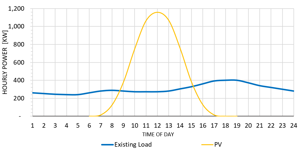
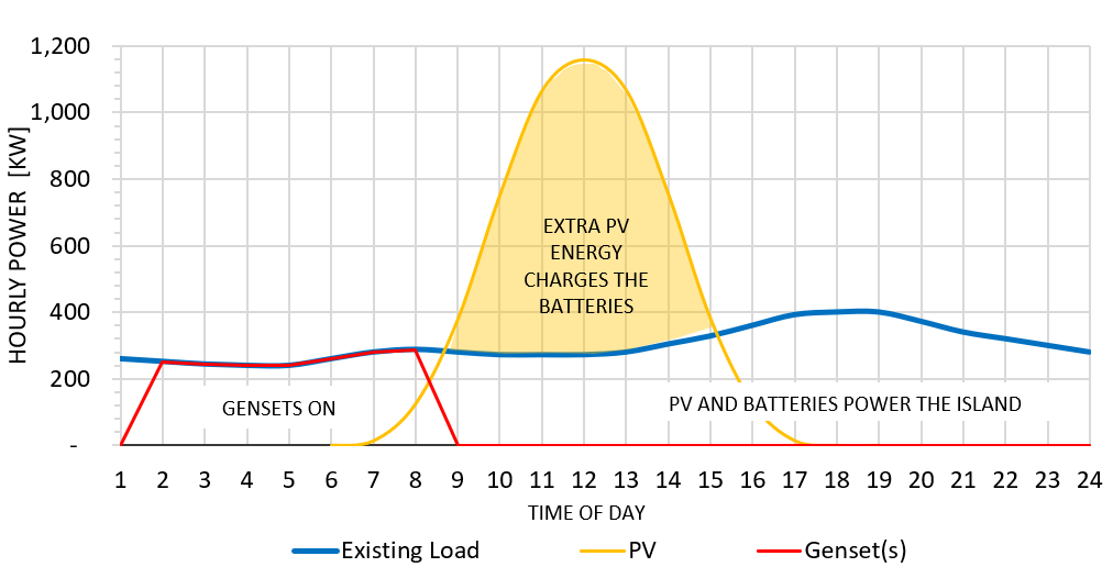
Figure 2 shows the typical daily performance of this LCOE microgrid. Depending on the sunshine and daily energy and when that energy is used during the day, the PV and battery plant will power the island until late in the night. In this typical example that is until 2:00 am. Then the gensets power the island until the sun rises. On some days the gensets might not start or run at all. And on some cloudy days with high occupancy loads the gensets may run all day. This balances out over the course of a year to achieve the expected annual targets.
Optimizing With Monte Carlo Simulation
This scenario of changing load and sunshine is a good candidate for computerized simulation using statistical analysis. Scientists and economists use Monte Carlo simulations for everything from predicting the path of a hurricane to estimating the future price of consumer goods. We use a Monte Carlo simulation for this optimization and sensitivity analysis based on a uniform probability distribution.
This optimization process starts with understanding the operating goals and the energy use patterns. Accepting that the 100% annual offset, or “net zero” or “zero carbon” isn’t realistic, our projects usually target a percent of annual diesel reduction balanced against budget and available land area or else the LCOE solution.
Here are the high-level steps.
- Define the daily energy consumption and power demand throughout the year.
- Estimate the cost for building and operating the PV system, battery plant, and diesel gensets.
- Combine that with a weather data set describing the sunshine and temperature throughout the year.
- Run an hourly simulation with these three data sets, applying a variability and sensitivity to get a range of results.
The first step is to define a daily power curve for every day or month for a whole year. Most business operations have some days during the week where loads are higher, or others where occupancy is higher for certain weeks or months during the year. Whatever the nature of the variability, the simulation starts with defining this profile for the entire year.
Then we add the local weather conditions to the simulation. This is a weather file that provides the expected sunshine and temperature for every hour of the year based on the historical database for the locale. This affects the power and energy produced by the PV system.
The hourly energy and weather aren’t consistent numbers, and that is where the simulation model becomes important. The model varies the Load and Weather curves through the course of the year, a probability distribution, and runs thousands of simulations with different combinations of that variability. The result is the expected performance of the project – the PV system and battery plant, the expected power and energy use, the expected runtimes of the gensets, and the expected cost of energy (including CapEx and OpEx).
For instance, the sample above with a daily power peak of 400 kW might vary from 380 kW to 420 kW for a specific day of the year. Or the weather might vary from full sun to partly cloudy for that same day. Multiplied by 365 days and evaluated over a few thousand model iterations.
We use the HOMER ® platform from Underwriter’s Laboratory (UL) for this Monte Carlo analysis. HOMER ® calculates the optimum sizing for the PV generation, battery storage, and genset plant based on diesel displacement and LCOE. The major system variables include the capital cost and replacement cost for the PV system, battery plant, and gensets, life cycle for all these components, and operating and maintenance expenses.
The simulation helps to understand the expected performance with much greater certainty. This helps to avoid under- or over-sizing components, and optimizes the investment based on the operational goals. For instance, as how many hours a day or a year will the gensets run, the service life of the batteries (based on total energy throughput), how much fuel will be used over time, and what are the expected O&M costs.
Load Profiling
The Load profile starts with the expected hourly power demand for all 8,760 hours in a year. For the microgrid subject of this report, the load varies significantly by month. That is driven by occupancy and climate (the need for air conditioning). This could also be 365 different load curves for every day of the year, or 52 different weekly load profiles, but for this example the load is assumed to be consistent for each month.
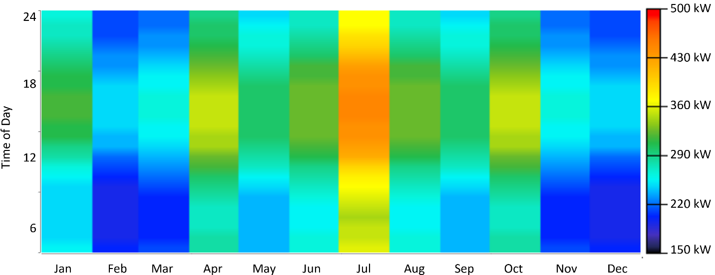
HOMER ® uses this graphic format, a “D-Map”, to show a year of data in one picture. The D-Map in Figure 3 is a D-Map of the 12 different monthly load curves.
The day of the year is along the bottom x-axis, and hour of the day on the left vertical axis. The scale on the right axis shows the colors corresponding to site power demand at any time of the year.
This Load D-Map is not applying any variability. The daily load in the D-Map is the same for every day of each separate month. In other words, the color (power load and the daily energy) moving from left to right through any month doesn’t change.
3 : Annual Load D Map, No Variability
Interpreting this Load D-Map:
Overall the power demand ranges from 175 kW (dark blue) to 430 kW (orange). As the day progresses from midnight to midday to evening (moving from bottom toward the top of the D-Map), the power demand is lowest in the morning (dark and blue) and reaches a daily peak (yellow to orange or red) between 1 pm (13) and 5 pm (17). July is a peak electricity demand month, resulting from higher occupancy and air conditioning loads. February and December are the lowest demand months.
For comparison, the months of April and October in Figure 3 are graphic representations of the daily power curve shown in Figure 1 and Figure 2, above.
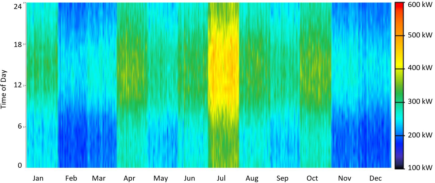
In the real world, the load for each month is never the same day to day. To account for this variability, HOMER ® applies a variability to the load data set. In the case of this project, it is a 3.5% variation, and that is the load D-Map in Figure 4. This now simulates a variability resulting from different activities and the impact of the local weather. (Note the scale on the color bar legend is not consistent between D-Maps.)
Defining the Lcoe Microgrid
Usually the primary objective is to define system capacities that deliver the lowest Levelized Cost of Energy (LCOE) 1 and assess the expected performance for the various microgrid components. These are useful for assessing warranty duration, or fuel deliveries, or understanding a range of operational modes.
The first step is determining the cost of energy without the microgrid. For an existing diesel-powered site, that is the Operating Expense (OpEx) of the existing powerplant plus reserves for future overhaul or replacement of old gensets. For a new electricity system, HOMER ® also can evaluate the initial capital investment for purchase and installation of new gensets.
The OpEx is the fuel cost plus the operation and maintenance (O&M) cost. Fuel cost is the largest part of the energy OpEx. In this case, the cost for landed diesel fuel averages $4.00 per gallon. Using either the site fuel and energy data, or the genset manufacturer’s performance graphs, that corresponds to approximately $0.30 per kWh for fuel. (Note that in 2023 that cost is $5.00 per gallon or more, plus VAT).
The O&M consists of preventative maintenance like oil changes, plus ongoing upkeep, cycle replacements, corrosion, and all sorts of emergency repairs. Typical range for O&M of diesel gensets is $15 to $20 per hour, or $0.07 to $0.10 per kWh. Usually diesel gensets in corrosive salt environments trend to the high end of that scale.
Reserves for future replacement typically are in the range of $1 to $3 per hour, or $0.01 to $0.03 per kWh. This is based on a typical diesel genset running 60,000 to 80,000 hours between major overhauls or replacement.
This results in a total non-fuel OpEx of $0.08 to $0.13 per kWh for O&M plus reserves. That is added to the fuel cost to calculate the existing, diesel-only cost of energy: we used $0.40/kWh for this project. This does not include insurance or maintenance of the distribution system, because those costs will remain even with a hybrid microgrid. It also does not include any “externalities” such as the cost of cleaning up fuel spills, environmental permitting and compliance, or regulatory testing. These costs could be added to the OpEx O&M cost but are not included for this example project.
Once the simulation is programmed with these data sets, we find the most useful result is the estimation of LCOE and the amount of energy produced from the PV array. This is roughly equal to the percent reduction of diesel fuel consumption.
1 Levelized Cost of Energy (LCOE) is calculated as the present value of the total cashflow of ownership over the life of the project divided by the total lifetime energy produced and used by the microgrid.
Figure 5 (full scale) and Figure 6 (expanded scale) show the resulting LCOE plot for this sample project. There are two system options that delivered the best performance with varying capacities of PV producing the curves. Option 1 uses a 4 MWh battery plant, and Option 2 uses a 6 MWh battery plant. The X-axis is the PV Fraction, or how much of the load is satisfied by the PV system. Above we are referring to this as the diesel reduction. The Y-axis is the cost of energy (COE).
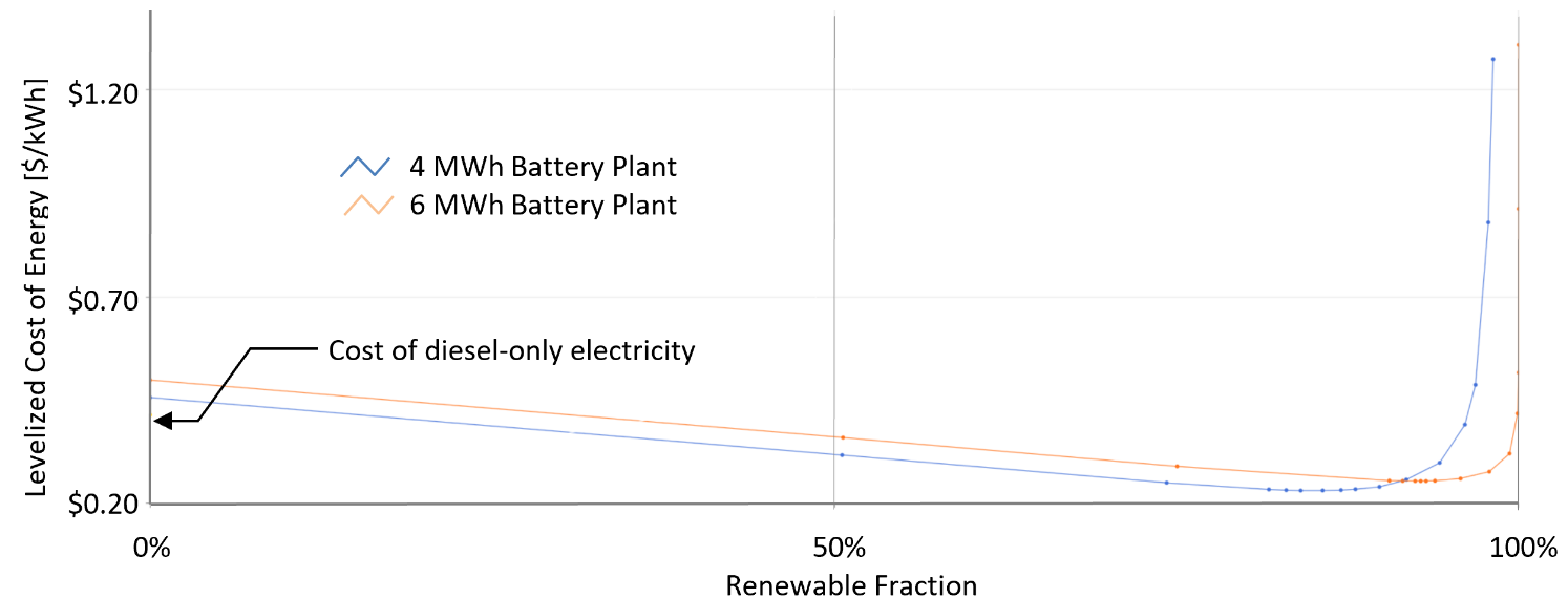
This indicates the lowest LCOE (LLCOE) is approximately $0.22/kWh using the 4 MWh battery. This corresponds to an 85% PV fraction (the red arrow in Figure 6). That means the cost of energy is reduced by almost half over the life of the microgrid and overall only about 15 to 20% of the electricity is produced from the diesel powerplant.
The Option-2 system, the orange curve, is the larger 6 MWh battery. The larger battery with more PV results in a greater Renewable Fraction (the bottom of the curve is further to the right) meaning less runtime on the gensets and more electricity from the PV system, but higher cost of energy (roughly $0.02 to $0.03 more per kWh). The numbers added above the curves are the PV capacities, in kW, for each point on each curve.
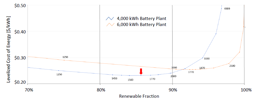
Figure 5 also shows that the cost of energy for 0% renewables is approximately $0.50/kWh. That is higher than the cost of diesel electricity by itself. The reason for that is if the microgrid is constructed but not used, that would be increasing the cost of the diesel electicity. Hence the “imaginary” cost increase over the cost of diesel-only electricity.
Also of note is that the cost of energy increases significantly as the PV fraction goes beyond the LLCOE and approaches 100%. This outcome is considered above in the Background section discussion of a net-zero target.
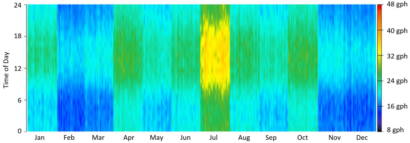
The fuel consumption D-Maps are a good graphical representation of overall performance. Figure 7 shows the annual diesel consumption existing conditions without the microgrid. This looks alot like the Load D-Map shown in Figure 4, since the diesel consumption varies directly with the load. The difference between these two D-Maps are the color scale units and values.
When the microgrid is operational, the overall diesel consumption is expected to look like Figure 8 for the all of the gensets in the powerplant combined. The most obvious difference is the vast amount of black area, corresponding to the gensets not running at all. Then, as with the other D-Maps, the genset power and diesel consumption is correlated to the color compared to the scale on the right.
First, note that the color graphical scale is different between Figure 7 and Figure 8. The small orange spots in July showing in Figure 7 indicate approximately 40 gallons per hour (gph) or roughly 550 kW of power demand. These occur only in July. A green color in Figure 7 is approximately 28 gph, or roughly 380 kW of power demand.
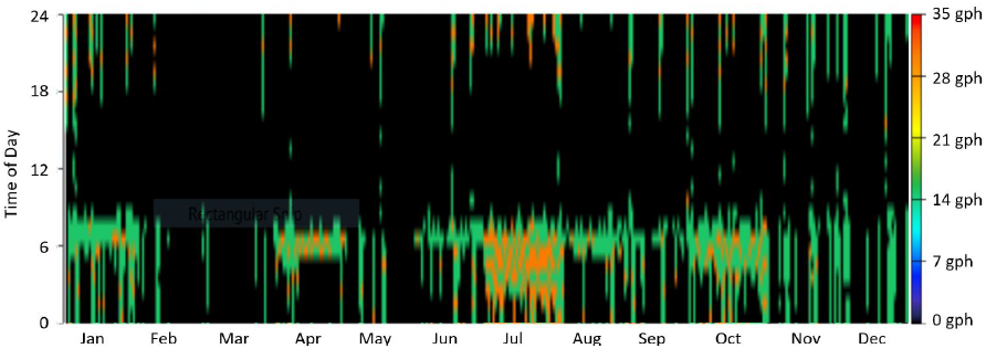
Most of the fuel consumption in Figure 8 is green, corresponding to a lower range of 15-18 gph, with a small amount of orange corresponding to 26-30 gph. By far most of the time represented in Figure 8 is black. That means the gensets are shut down completely and all the energy is being supplied by the sun.
Operationally, this means the diesel powerplant will operate most days at least for 2-4 hours in the morning from 4 am to 8 am until the sun rises and the PV system starts producing electricity. Some days the gensets will not run at all (much of February and March, for instance) and other days will have more load, more clouds, and more genset runtime (July, again, for example).
Quality Control Process
Remember these two points as we start this discussion. (1) The total energy consumed daily or annually affects the size of the PV system. (2) The shape of the daily power curve (when energy is used during the day) affects the size of the battery plant.
It is important to note that the HOMER ® simulation is not a guaranteed performance profile. The primary variable that affects its validity is the actual amount and timing of power and energy on a daily and annual basis.
For example, if the energy consumption really occurs at night when it is expected to occur during the day, that will change the diesel reduction. That could result in curtailment (not using) some of the PV energy during the day, not having enough battery plant capacity for the nighttime demand, and the gensets running more at night.
Imagine a site that has a large ACTUAL peak in its load after daylight hours (Figure 9). But the EXPECTED load profile used in HOMER ® had peak energy usage during peak sun hours of 10 am to 4 pm (“10” to “16”).
The PV size would be the same in both cases, but the HOMER ® model would recommend a smaller battery plant than what really is needed. That is because the actual load occurs after sun hours as opposed to the simulated load occurs during the same hours as the most sunshine.
In this case, the gensets would run much more than anticipated. And as importantly, much of the PV electricity would be curtailed, or not used, because the load doesn’t occur until later in the day and the batteries would be fully charged during daylight hours. This is a good example of garbage-in-garbage-out, and something to be avoided in HOMER ® modeling. That is why a Quality Control review of the modeling process is important.
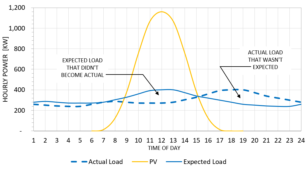
9 : Variation Between Expected and Actual Power Curves
Energy Efficiency and Demand Reduction
Helping our clients manage their energy use is a core part of our business philosophy. This involves reducing energy consumption, managing power demand, and controlling when energy is used during the day. This approach can significantly reduce the cost of a microgrid and the diesel OpEx and increase the renewable penetration.
In most cases, a reduction of 5 to 10% of electricity demand can be achieved with an investment that will pay back in 2-3 years. Those include lighting upgrades, system controls, human factors, and managing when energy systems operate.
A lighting upgrade is an effective way to achieve this reduction. Many buildings have inefficient incandescent or fluorescent lamps in areas that are lit 24 hours a day. Turning off those lights when not needed and upgrading to more efficient LED lamps will have a significant effect on energy consumption. That will result in reduced need for PV generation and battery capacity.
While the lighting upgrade reduces power and energy overall, another effective tactic is to change when energy is used. For instance, refer to Figure 9 and consider an island resort that has a reverse osmosis water purification plant. In most installations, that plant operates at night to balance the genset load across the 24 hours of a day – resulting in the dashed blue load line.
If that RO plant can be reconfigured to operate during the day, then its daily power curve would be more like the solid blue load line. That is an example of demand regulation. The total energy usage is the same, and the size of the PV plant does not change. But the time that energy is used changes to reduce the size of the battery plant.

