Here are two basic engineering question that apply to most solar projects.
- At what tilt should the modules be mounted?
- Should the orientation be “portrait” or “landscape”?
Getting the answers right should be part of every design engineer’s Quality Assurance process. They also are important to the system owner, because in some ways the solar installer and the project owner may have opposing interests. And decisions driven by the wrong reasons can mean the difference between a project that successfully produces and meets expectations for decades, or doesn’t.
Tilt is the angle of the module to the horizon. Usually modules are installed with a tilt of 5 degrees or as much as 30 degrees.
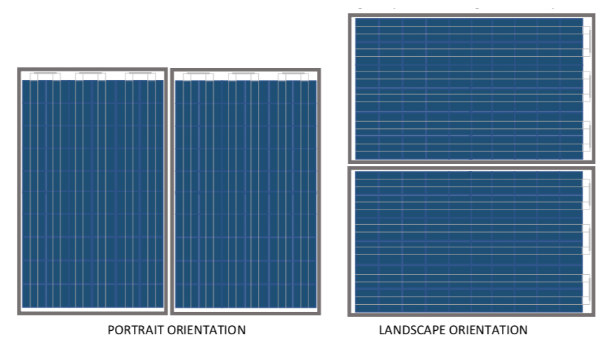
Orientation of “portrait” means the module is mounted with the short side parallel to the ground. Like a portrait painting. “Landscape” is the other way, with the long side parallel to the ground. Like you are looking at a landscape painting.
Spoiler alert: here are the conclusions of this article in case you don’t want to read it all.
- At northern latitudes where snow occurs with regularity, it is best to mount modules at a higher tilt and in landscape orientation.
- At southern latitudes where thankfully there isn’t any snow, we recommend mounting modules at a minimum tilt of 5 degrees and in portrait orientation.
- The lower the tilt, the more important it is the orientation be portrait.
- Modules should not be mounted at a zero, or flat, tilt. It is an extremely rare case where that is a good engineering idea.
Before we dig into the meat of this topic, here’s a quick refresher on the difference between power and energy. Power is measured in kilowatts or megawatts, kW or MW, and is like the speedometer of a car. Energy is measured in kilowatt-hours or megawatt-hours, kWh or MWh, and is like the odometer of a car.
MODULE TILT
Tilt is a compromise that is affected by wind, snow, allowable mounting area, strength of the ground or structure, latitude, energy cost, and the balance between desired energy cost, energy production, and season of the year. It is a true engineering decision – problem solving and decision making when all resources are limited, including money.
Sometimes tilt is a really easy question to answer. Like if the array is going on a pitched roof: the modules should have the same tilt as the roof. Some may disagree with me on this, but I believe it is difficult to make a case based on safety, performance, and aesthetics that mounting modules with a different pitch and azimuth than the sloped roof is a good idea. There are exceptions to everything, but generally, this approach invites debris accumulation, almost never gets engineered properly for wind force on the roof attachments, and it does nothing for the argument that solar panels lack aesthetic appeal.
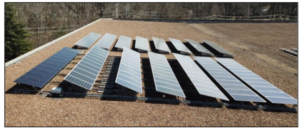
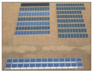
Other than a sloped roof, higher tilt angle usually means fewer modules can fit on the available roof or ground area. That is because the higher the tilt, the longer the shadow cast by one row of modules, and that requires more space between the rows to avoid shadowing. Take a look at the next two pictures, of a small testbed project we built 6 years ago. The rows have varied tilt (and also different power electronics, module-level optimizers, and module types throughout), and you can see how far apart the rows need to be to keep from casting a shadow on their neighbor to the north (left, in the picture). The two rows at the south (right) in the top picture are at zero tit, and could be mounted right next to each other. But we left a 6” walkway between them to allow for easier maintenance.
 Usually a no-slope array has no pathways like this, as can be seen in the later pictures in this article. With no separation between rows, it is pretty much impossible to maintain or replace modules without putting the weight of a person on the frames or glass.
That’s the first reason to avoid zero-tilt arrays. While walking or kneeling on the modules probably won’t break the glass, it often results in microcracks in the cells and internal electrical pathways. They might not fail today, but their performance life surely will be shortened. Don’t ever let a service technician tell you it is OK to walk on the modules!
 More modules on the roof (or the ground) means more kW or MW of power capacity. That also means the system has a higher price and more profit margin for the installer.
So why is it not a good idea to install more modules and more power?
Most system owners want to produce energy and lower their cost of energy. The number of modules (the power capacity) isn’t the end goal by itself. And installing an array with zero tilt anywhere in the US or Caribbean will result in a higher cost of electricity.
Zero tilt = more power capacity.
Zero tilt = more expensive project.
Zero tilt = more expensive energy.
Zero tilt = more difficult ongoing maintenance, troubleshooting, and repairs.
A drawback to using the optimal tilt to get the lowest energy cost is related to wind. The higher the tilt, the higher is the wind force, because the modules are sticking up higher. That means more ballast weight or more attachment points for a rooftop array, or more or deeper foundations for a ground mount.
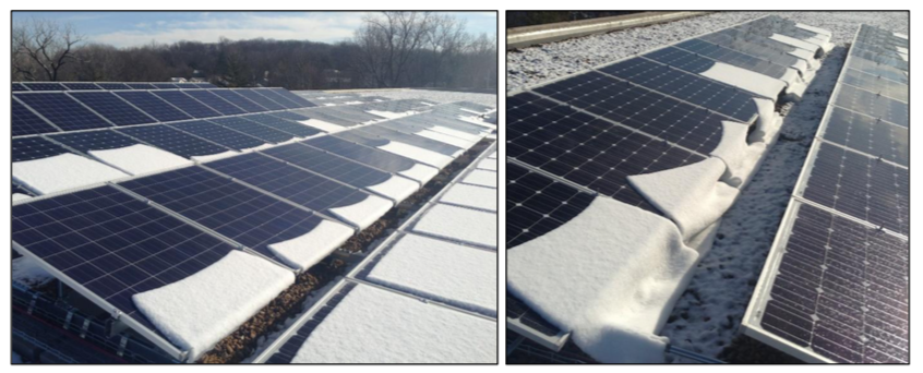
But again, that’s an engineering compromise. Because if the site has a snow problem (and as far as I am concerned, anywhere with snow has a problem), then higher tilt sheds snow easier and requires less structural strength for the weight of the snow. The next two pics show how modules shed snow.
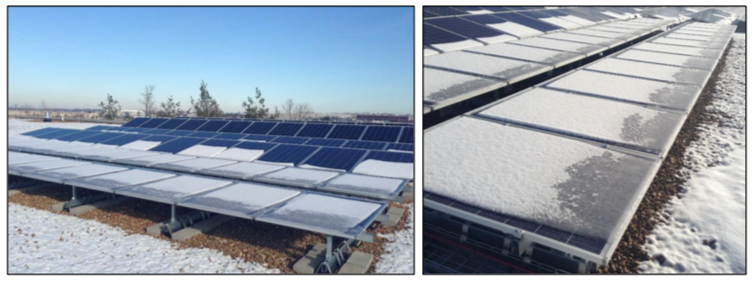
The lower the tilt, the more snow accumulation and the longer the snow hangs around. On the zero-tilt modules, the snow doesn’t even slide off; it just turns to ice. That’s the same thing that happens when there is rain, by the way.
Below it is clear that the higher the tilt (left rows) the faster the snow clears. The pic on the right shows the way snow tends to slide off in a sheet fashion.
So the project engineer has to weigh all these factors in deciding the tilt to build in to the project. Then the structural engineer has to do their magic and analyze all the pieces of the structure.)
Besides snow performance, why is zero tilt a bad idea?
When modules are flat, they produce less energy (unless installed at the equator). That means the energy produced per dollar of array cost will be lower, and the overall financial performance will be worse. The table, below, shows three array options installed in the Midwest US, although the performance variations are similar anywhere in the US or Caribbean. The “Solar Yield” is how much energy is produced by each module, and it is clear the yield is highest at a 15-degree tilt angle. The energy cost also is lowest at the 15-degree tilt, about 19% lower than at zero tilt.
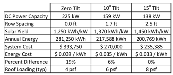
ASSUMPTIONS
Rooftop installation, 40o N latitude
Available rectangular footprint is 13,000 square feet
Additionally, when modules are mounted flat, it causes a problem with soiling and possibly the warranty on the modules.
Rain falls through the atmosphere and picks up dust from the air. All rain has a certain amount of dust and particulate matter in it. When modules are mounted at a five to 20-degree tilt, the rain runs down the glass to the bottom edge and then over the frame and to the roof or the ground. When the rain stops, there is a little sliver of water trapped at the lowest edge of the module at the depth of the frame above the glass (roughly a few millimeters). When the water evaporates, the suspended dust dries on the glass and becomes a brown, crusty deposit, again, on the lowest edge of the module surface against the frame. The higher the tilt, the thinner that sliver of dirt.
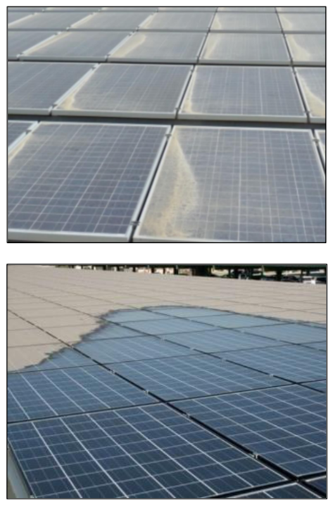 When modules are mounted flat, the water doesn’t run off, until the pool formed by the frame above the glass overflows. Like what happens to a swimming pool when there is a lot of rain, and the pool floods.
When the rain stops, the module has a puddle of water on top of the glass. That puddle is filled with dust, like before, and when the puddle evaporates, it leaves the load of dust deposited over the entire glass surface of the module.
As a result, flat-mounted modules can be clean one day, and after one rain, they look like they haven’t been washed in years. The immediate loss in productivity can be two to 3%, just from one rain event! Below is a pic of a flat array in a dusty area with a lot of industrial activity that results in extra airborne particulates, in the process of being cleaned.
As if dirt and loss of production wasn’t bad enough, flat tilt can void the warranty of some modules. That is because the ponding water has a lot of contact time with the seal between glass and metal frame, and can damage the seal. Water behind the glass is a bad thing, and if on a flat array, may not be covered by warranty.
MODULE ORIENTATION, LANDSCAPE OR PORTRAIT
There is little difference overall between portrait or landscape with regard to how many panels can be put on the roof or ground at a specific tilt angle. Depends more on the shape of the mounting area than anything else. Sometimes landscape will work out better and sometimes portrait is the best fit.
However, the decision to mount landscape or portrait is influenced by the installation location, potential for snow and shading.
Solar modules usually are made up of 60 or 72 or 96 individual solar cells. These are connected within each module in series circuits of 20 or 24 or more, and then those series circuits are connected in series so that each module’s voltage is the sum of all the cells. For example, cells produce around 0.5 V, and for a module that has 60 cells, that results in a module voltage or 30 V.
When one or more of the cells is shaded, then the series current cannot flow through that cell. That can cause problems with localized heating of that shaded module and a rise in the voltage. That shading can
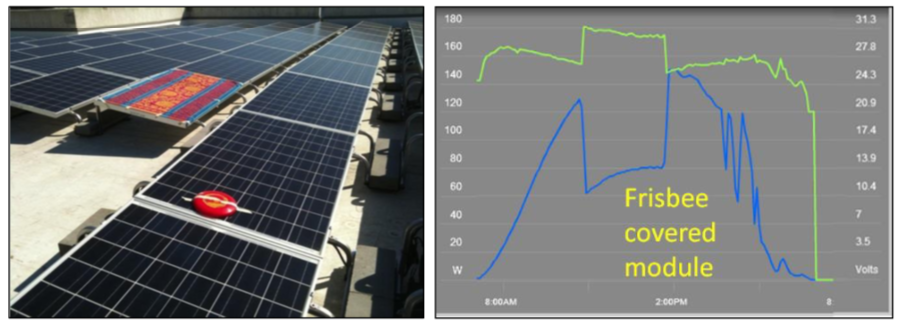
be caused by something as simple as a leaf, or accumulated dirt, or maybe even a frisbee (see image, below, from a test we conducted a few years ago to measure the impact of shading).
The green line in the production curve trace is module voltage, and the blue line is module current.
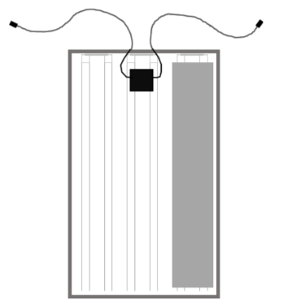 If the voltage and heating are high enough, there is a potential for fire. To avoid that, manufacturers design the modules with diodes between the groups of cells that will keep this from happening by bypassing any shaded cells or modules. There usually are three bypass diodes in each module, and each diode is connected to 1/3 of the cells, as in this diagram.
Now let’s revisit the shading design and ignore the situation where a leaf or frisbee randomly covers one cell. Let’s look at what happens with modules in portrait or landscape, when something causes shading. This can be snow, or as in the next photograph, when someone installs the fence too close to the array!
When the snow or the shadow of the fence (or the crusty dirt on the glass) cover part or all the cells on the short side (module in portrait) then the entire module is going to be bypassed and not producing energy. When the module is in landscape and the lower edge is shaded, then only 1/3 of the module is affected and the power and energy could still be at 2/3 capacity.
Modules are built with a wider border on the short side. That means when the modules are dirty on the bottom edge (not zero tilt) then there can be more dirt accumulated before the cells start to get shaded. While I do not know this for a fact, I believe this is because manufacturers intended modules to be mounted in portrait to provide better performance with dirt crust shading on the bottom edge.
For arrays installed where snow falls, landscape orientation will get 1/3 and then 2/3 of the module producing during the hours or days when the snow slides off the glass as it melts. That is why we recommend landscape orientation in areas subject to snow.

